Silicon microring near its size limit
A microring is a waveguide, a strip of silicon that guides light by total internal reflection, closed into a loop. Light whose wavelength fits a whole number of times around the loop returns in step with itself and builds up: a resonance. Rings beside a straight waveguide pick single wavelengths out of it, so they serve as filters, modulators and sensors, and a smaller ring takes less area and power. Shrinking has a limit: in a tight bend the guided mode, the field pattern the waveguide carries, cannot follow the curve, and its outer edge radiates into the cladding. The quality factor Q measures how long the ring stores light; it is the resonance wavelength divided by the resonance's width, so a higher Q is a sharper filter. The intrinsic Q, that of the ring alone, falls steeply as the radius shrinks. Filters and modulators need an intrinsic Q from about ten thousand to a few hundred thousand, so that fall sets the smallest useful ring.
This notebook rings down two silicon rings from Xu, Fattal and Beausoleil, Opt. Express 16, 4309 (2008), each sized to resonate at the paper's 1546 nm, and fits their intrinsic Q: Q doubles every 103.7 nm of radius, against the paper's 106.5 nm. Q itself reads about a quarter above the paper's at the same radius.
Parameters
The design numbers are the paper's, then its stated Q at two radii. The larger radius is the paper's 1.5 µm, trimmed so the ring resonates at 1546 nm, where the paper held every ring; a resonance moves by 0.58 times the fractional change in radius. The mesh has 20 cells per wavelength in each medium. The 10 ps ring-down is about a quarter of the photon lifetime: the fit reads Q from the decay rate. The pulse rings one resonance, not its neighbours. The PML sits 0.8 µm out, room for the radiated light, and a symmetry plane at the silicon mid-plane, where the mode is even, halves the run.
import matplotlib.pyplot as plt
import numpy as np

import photonhub as ph
from photonhub.analysis import ResonanceAnalysis, select_resonances
# design, the paper's Sec. 2
w = 0.450  # ring waveguide width (µm)
h = 0.250  # silicon thickness, oxide all round (µm)
wlen0 = 1.546  # wavelength every ring resonates at (µm)
radius = 1.493  # centreline radius (µm); Δλ/λ = 0.58 ΔR/R
radius_small = 1.393  # smaller ring, trimmed the same way (µm)
paper_q = 46600  # paper, stated intrinsic Q at paper_r
paper_r = 1.5  # paper, radius of that Q (µm)
paper_q_small = 20000  # paper, stated intrinsic Q at paper_r_small
paper_r_small = 1.37  # paper, radius of that Q (µm)
paper_tol_nm = 2.2  # paper, every ring within this of wlen0 (nm)
# simulation choices
cells_per_wlen = 20  # mesh cells per wavelength, in each medium
record_ps = 10.0  # ring-down recorded (ps)
fwidth_hz = 3e12  # pulse bandwidth (Hz)
clearance = 0.8  # silicon to PML (µm)
pml = 12  # PML layers
symmetry = (0, 0, 1)  # even mirror at the silicon mid-plane
probe_deg = 52.0  # first probe, from the dipole (degrees)
samples_per_period = 16  # probe samples per optical period

f0 = ph.c0 / (wlen0 * 1e-6)  # resonance frequency (Hz)
wlen = np.linspace(wlen0 - 0.004, wlen0 + 0.004, 9)  # profile wavelengths (µm)
Geometry
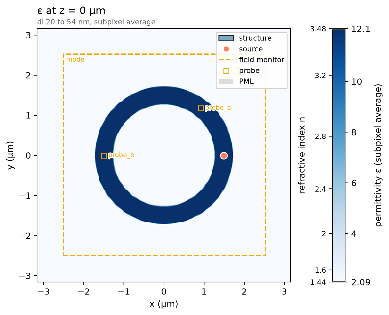
The ring is one ph.Cylinder along z with a hole through it: radius_um is
its outer wall, half a width beyond the centreline, inner_radius_um its inner
wall, and length_um the silicon thickness, centred on the origin.
ph.Structure gives it the library's silicon; the oxide cladding is the
background.
ring = ph.Cylinder(
    axis="z",
    center_um=(0.0, 0.0, 0.0),
    radius_um=radius + w / 2,  # outer wall
    inner_radius_um=radius - w / 2,  # inner wall
    length_um=h,
)
structures = [ph.Structure(geometry=ring, medium=ph.materials.Si)]
Simulation
ph.PointDipole is a point source; on the centreline, polarised across the
guide and driven by a short ph.GaussianPulse, it rings the mode. With no
ports, there is no mode window to size. The dipole excites a standing wave, so
the two ph.TimeMonitor probes, which record the field against time, sit
where no zero of that wave can fall: 52° round and at the half turn. They
sample about 16 times per optical period, a step count set by the solver's
time step. A ph.ProfileMonitor on the mid-plane records the mode; its
ph.Apodization opens after the pulse.
pulse = ph.GaussianPulse(freq0_hz=f0, fwidth_hz=fwidth_hz)
source = ph.PointDipole(center_um=(radius, 0.0, 0.0), polarization="Ex", source_time=pulse)
dz = wlen0 / (ph.materials.Si.n(wlen0) * cells_per_wlen)  # finest cell, in silicon (µm)
dt = 0.99 * dz * 1e-6 / (ph.c0 * np.sqrt(3))  # the time step that cell sets (s)
interval = max(1, int(round(1 / (f0 * samples_per_period * dt))))  # steps per sample
angle = np.radians(probe_deg)
probes = [
    ph.TimeMonitor(
        name="probe_a",
        center_um=(radius * np.cos(angle), radius * np.sin(angle), 0.0),
        fields=("Ex", "Ey"),
        interval_steps=interval,
    ),
    ph.TimeMonitor(
        name="probe_b", center_um=(-radius, 0.0, 0.0), fields=("Ex", "Ey"), interval_steps=interval
    ),
]
t_start = 2 * pulse.source_end_time_s  # the pulse is over (s)
apodization = ph.Apodization(
    start_s=t_start, end_s=record_ps * 1e-12 - 2 * t_start, width_s=0.5 * t_start
)
mode = ph.ProfileMonitor.plane(
    "mode", "z", 0.0, wlens_um=wlen, fields=("Ex", "Ey", "Ez", "Hz"), apodization=apodization
)
ph.Simulation holds the setup. ph.Domain fits the box around the ring;
ph.Mesh grades the mesh, finest in the silicon, with subpixel averaging at
the walls. The run records a fixed ring-down with no early stop.
sim = ph.Simulation(
    domain=ph.Domain(clearance_um=(clearance, clearance, clearance)),
    mesh=ph.Mesh(cells_per_wlen=cells_per_wlen),
    background=ph.materials.SiO2,  # oxide cladding
    pml_num_layers=pml,
    symmetry=symmetry,
    structures=structures,
    sources=[source],
    monitors=probes + [mode],
    run=ph.RunSpec(run_time_s=record_ps * 1e-12, shutoff=0.0),
    wlen0_um=wlen0,  # the indices are taken here
)
sim.plot_index(z=0.0)
plt.show()
ph.run_local runs the solver on this computer; ph.cloud.run_quoted runs it
on a cloud GPU.
data = ph.run_local(sim, quiet=True)
# On a cloud GPU instead, with GPU and SOLVER from your closed-test guide:
# data = ph.cloud.run_quoted(sim, device=GPU, solver=SOLVER)
Field
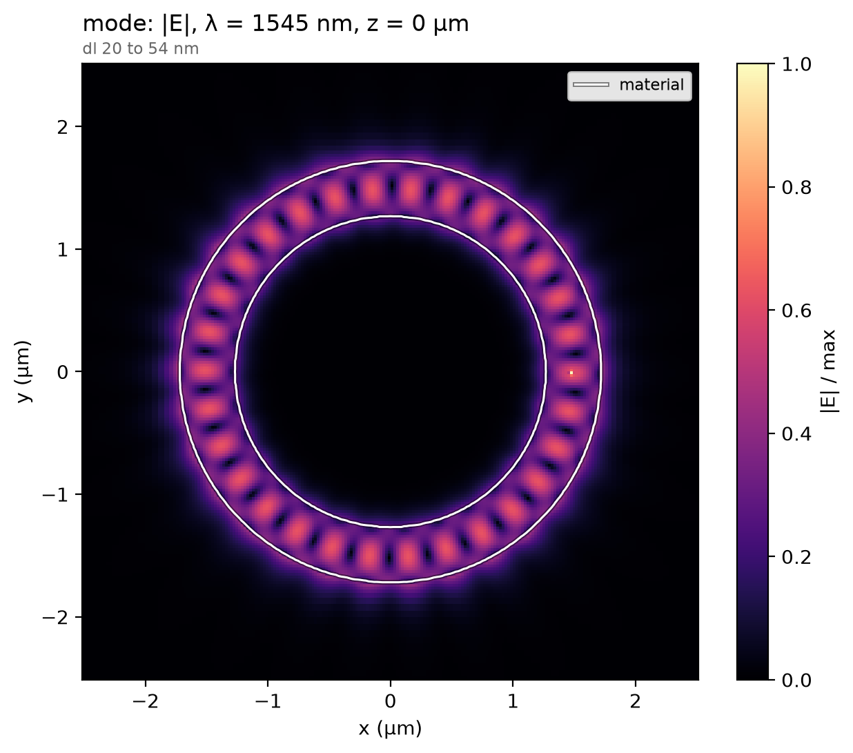
The ring resonates where its geometry puts it, so the profile is read at the recorded wavelength holding the most field. The mode circulates in the silicon and leans against the outer wall: that is the side the bend radiates from, and why a smaller ring leaks faster.
total = np.abs(data["mode"]).sum(("component", "x", "y", "z"))  # |E| summed per wavelength
f_map = float(total.idxmax("f"))  # the recorded frequency nearest the resonance (Hz)
data.plot_field("mode", field="E", z=0.0, freq=f_map)
plt.show()
Result
The resonance and the intrinsic Q come from fitting the decaying poles of the probes' summed ring-down after the pulse, between 1500 and 1600 nm, where the ring has one resonance.
def fit(run):
    # (resonance in nm, Q) of the strongest decaying pole from 1500 to 1600 nm
    names = ["probe_a", "probe_b"]
    ringdown = {name: run[name].sel(t=slice(t_start, record_ps * 1e-12)) for name in names}
    band = (ph.c0 / 1.60e-6, ph.c0 / 1.50e-6)
    poles = ResonanceAnalysis(freq_window=band, init_num_freqs=120).run(ringdown, names)
    top = select_resonances(poles, freq_window=band, require_decay=True, sort_by="amplitude")
    top = top.isel(freq=0)
    return ph.c0 / float(top.coords["freq"].values) * 1e9, float(top["Q"].values)


resonance, q = fit(data)
print(
    f"resonance {resonance:.2f} nm (paper: every ring within {paper_tol_nm} nm of "
    f"{wlen0 * 1e3:.0f} nm) | Q {q:,.0f} at R = {radius} µm"
)
The paper's question is how fast Q falls as the ring shrinks. The smaller ring
is the same simulation with the ring, the dipole and the probes moved to its
radius; sim.with_changes swaps them in.
ring_small = ph.Cylinder(
    axis="z",
    center_um=(0.0, 0.0, 0.0),
    radius_um=radius_small + w / 2,
    inner_radius_um=radius_small - w / 2,
    length_um=h,
)
probe_a = (radius_small * np.cos(angle), radius_small * np.sin(angle), 0.0)
probes_small = [
    ph.TimeMonitor(name="probe_a", center_um=probe_a, fields=("Ex", "Ey"), interval_steps=interval),
    ph.TimeMonitor(
        name="probe_b",
        center_um=(-radius_small, 0.0, 0.0),
        fields=("Ex", "Ey"),
        interval_steps=interval,
    ),
]
source_small = ph.PointDipole(
    center_um=(radius_small, 0.0, 0.0), polarization="Ex", source_time=pulse
)
small = ph.run_local(
    sim.with_changes(
        structures=[ph.Structure(geometry=ring_small, medium=ph.materials.Si)],
        sources=[source_small],
        monitors=probes_small,
    ),
    quiet=True,
)
The squares are the paper's stated Q at its two radii; Q doubles over a fixed step in radius. Ours sit 22 % to 25 % above the paper's at the same radius: the same trend, moved by about 30 nm.
resonance_small, q_small = fit(small)
doubling_nm = (radius - radius_small) * 1e3 * np.log(2) / np.log(q / q_small)
paper_nm = (paper_r - paper_r_small) * 1e3 * np.log(2) / np.log(paper_q / paper_q_small)
ph.viz.plot_comparison(
    np.array([radius_small, radius]) * 1e3,
    np.array([q_small, q]),
    stated=[
        (paper_r_small * 1e3, paper_q_small, "paper, stated (Q at 1370 nm radius)"),
        (paper_r * 1e3, paper_q, "paper, stated (Q at 1500 nm radius)"),
    ],
    xlabel="ring radius (nm)",
    ylabel="intrinsic Q",
)
plt.show()
print(
    f"R = {radius_small} µm: resonance {resonance_small:.2f} nm, Q {q_small:,.0f} | "
    f"Q doubles every {doubling_nm:.1f} nm of radius (paper: {paper_nm:.1f} nm)"
)
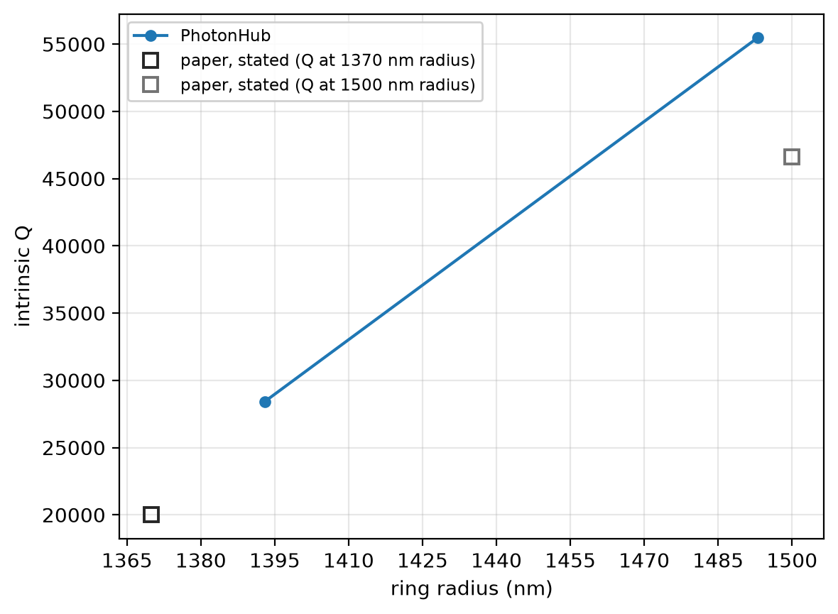
R = 1.393 µm: resonance 1545.73 nm, Q 28,427 | Q doubles every 103.7 nm of radius (paper: 106.5 nm)
At 20 cells per wavelength the radius step over which Q doubles reads 103.7 nm at 1546 nm, from one mesh, not shown converged; the paper's 3D FDTD, 106.5 nm. The run uses a graded mesh of 20 cells per wavelength in each medium, subpixel averaging on, non-dispersive silicon and oxide, 12 PML layers and one mirror plane at the silicon mid-plane.